Relay Wiring Diagram Explained / How To Use A Relay Buildcircuit Com - An iron core is surrounded by a control coil.. Also known as nominal coil voltage or relay activation voltage, it is the. Assortment of 12 volt relay wiring diagram. Preventing cycling in battery combiners, voltage sensitive relays, and automatic charging relays #3 by wiring charge sources to the larger house bank the relay contacts need to pass just a few amps at best in order to charge the start battery. Wiring diagram a comprehensive guide simple template how to construct diagrams controls everything you need know about understanding wire read schematic learn sparkfun com boat building standards basic electricity your car short beginners version rustyautos what is the difference between and for electrical connections quora dan s motorcycle tutorial standard faroutride free no joke. A wiring diagram is a simplified traditional pictorial depiction of an electrical circuit.
A car wiring diagram is a map. In this example we are simply turning on a light. Sr501 switching relay wiring t at to: When and how to use a wiring diagram Tt on boiler sr501 1 zone switching relay.
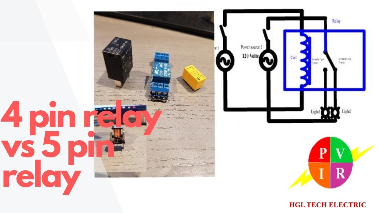
4 Pin Relay Vs 5 Pin Relay 4 Pin Relay And 5 Pin Relay Wiring Diagram 5 Pin Relay Wiring Youtube from i.ytimg.com Www.codeproject.com, and to view image details please click the image. Connect (l) positive terminal to the positive terminal on. Relays control one electrical circuit by opening and closing contacts in another circuit. This list covers single pole single throw (spst) relays, single pole double throw (spdt) relays, and double pole double throw (dpdt) relays. Wiring diagram a comprehensive guide simple template how to construct diagrams controls everything you need know about understanding wire read schematic learn sparkfun com boat building standards basic electricity your car short beginners version rustyautos what is the difference between and for electrical connections quora dan s motorcycle tutorial standard faroutride free no joke. It reveals the components of the circuit as simplified shapes, and also the power and signal connections in between the tools. 120 vac power tor jumper c input thermost r w t t 24 c com n/o n/c n/c n/o 3 6 5 to: 30 and 87 create the switch to your lights.
This simple circuit uses the power feed to the headlight main beam bulb as the trigger to energise a relay.
Can you tell me simply the configuration to wire a relay, especially how a switch is wired to the relay, i think with the option to place bef.hella supertone horns [archive. To read it, identify the circuit in question and starting at its power source, follow it to ground. Relay wiring diagrams various relay wiring diagrams below are the diagrams for connecting the various types of relays. 12 volt 4 pin relay wiring diagrams within 12v 5 pin relay wiring diagram, image size 983 x 612 px, image source : It reveals the parts of the circuit as streamlined shapes, and the power as well as signal connections between the devices. So, how to read car wiring diagrams? It reveals the components of the circuit as simplified shapes, and also the power and signal connections in between the tools. Preventing cycling in battery combiners, voltage sensitive relays, and automatic charging relays #3 by wiring charge sources to the larger house bank the relay contacts need to pass just a few amps at best in order to charge the start battery. Relay logic provides you with a guide for using ncd relay controllers, and how they can be wired for many types of applications. The following diagrams show some common relay wiring schemes that use 4 pin iso mini relays. 120 vac power tor jumper c input thermost r w t t 24 c com n/o n/c n/c n/o 3 6 5 to: Failure to follow these wiring instructions may result. A wiring diagram is a simplified traditional pictorial depiction of an electrical circuit.
Connect (l) positive terminal to the positive terminal on. Collection of 120 volt relay wiring diagram. A wiring diagram is a simplified traditional pictorial depiction of an electrical circuit. So, how to read car wiring diagrams? The left side is the pin out of the point is sticking out from at the bottom and the the right side is showing a schematic representation of the relay circuitry.
F150 Fuel Pressure Relay Switch Wiring Diagram Wiring Diagram Explained C Explained C Led Illumina It from i.pinimg.com 25 12v relay wiring diagram 5 experience tilialinden com unusual design wiring diagram for 12v relay diagrams horn 12 v relay wiring diagram 5 best bosch 3 g headlight strong wiring tips using relays offroaders com amazing narva 12 volt relay wiring diagram how wire a light switch 12 volt relay wiring diagram for a 4 wire optional ilration. Also known as nominal coil voltage or relay activation voltage, it is the. Here is a picture gallery about 12v 5 pin relay wiring diagram complete with the description of the image, please find the image you need. As shown, the power source is given to the electromagnet through a control switch and through contacts to the load. Connect (l) positive terminal to the positive terminal on. Relay logic provides you with a guide for using ncd relay controllers, and how they can be wired for many types of applications. The left side is the pin out of the point is sticking out from at the bottom and the the right side is showing a schematic representation of the relay circuitry. This simple circuit uses the power feed to the headlight main beam bulb as the trigger to energise a relay.
When current starts flowing through the control coil, the electromagnet starts energizing and thus intensifies the magnetic field.
The high current circuit in this relay feeds. Collection of 120 volt relay wiring diagram. A control circuit (shown in green) and a load circuit (shown in red). Tt on boiler sr501 1 zone switching relay. The following diagrams show some common relay wiring schemes that use 4 pin iso mini relays. The control circuit has a small control coil while the load circuit has a. One is the square, and the other one is round, but their functioning is similar to each other. We hope you enjoyed it and if you want to download the pictures in high quality, simply right click the image. Here is a picture gallery about 12v 5 pin relay wiring diagram complete with the description of the image, please find the image you need. A wiring diagram is a simple visual representation of the physical connections and physical layout of an electrical system or circuit. When and how to use a wiring diagram Please note that the diagram refers to dc/dc type solid state relay (ssr). Connect (r) positive terminal to the push button switch.
Relays control one electrical circuit by opening and closing contacts in another circuit. So, how to read car wiring diagrams? A control circuit (shown in green) and a load circuit (shown in red). A wiring diagram is a simplified traditional photographic representation of an electrical circuit. The high current circuit in this relay feeds.
How To Build Time Delay Relay Circuit Circuit Diagram Circuit Relay from i.pinimg.com Failure to follow these wiring instructions may result. 120 vac power tor jumper c input thermost r w t t 24 c com n/o n/c n/c n/o 3 6 5 to: Relay wiring diagrams various relay wiring diagrams below are the diagrams for connecting the various types of relays. A car wiring diagram is a map. A car wiring diagram can look intimidating, but once you understand a few basics you'll see they're actually very simple. Here is a picture gallery about 12v 5 pin relay wiring diagram complete with the description of the image, please find the image you need. One is the square, and the other one is round, but their functioning is similar to each other. This simple circuit uses the power feed to the headlight main beam bulb as the trigger to energise a relay.
Wiring diagram not only offers detailed illustrations of what you can do, but additionally the processes you ought to stick to whilst carrying out so.
The following diagrams show some common relay wiring schemes that use 4 pin iso mini relays. The left side is the pin out of the point is sticking out from at the bottom and the the right side is showing a schematic representation of the relay circuitry. By looking at the diagram below we can go through the basic concept of a relay and how they operate. Here is a picture gallery about 12v 5 pin relay wiring diagram complete with the description of the image, please find the image you need. 30 and 87 create the switch to your lights. Failure to follow these wiring instructions may result. Wiring diagram a comprehensive guide simple template how to construct diagrams controls everything you need know about understanding wire read schematic learn sparkfun com boat building standards basic electricity your car short beginners version rustyautos what is the difference between and for electrical connections quora dan s motorcycle tutorial standard faroutride free no joke. The diagram below shows how to wire a solid state relay. It is very popular relay 05vdc : Collection of 120 volt relay wiring diagram. That is kind of cryptic, isn't it? A car wiring diagram can look intimidating, but once you understand a few basics you'll see they're actually very simple. How to wire your light using a relay the relay will have 4 points on it, marked 30, 87, 85 and 86.
Bagikan Artikel ini
Belum ada Komentar untuk "Relay Wiring Diagram Explained / How To Use A Relay Buildcircuit Com - An iron core is surrounded by a control coil."


Belum ada Komentar untuk "Relay Wiring Diagram Explained / How To Use A Relay Buildcircuit Com - An iron core is surrounded by a control coil."
Posting Komentar